


Zhejiang ATTC Automotive Technology Service Co., Ltd. is honored as the 2025 Leading Service Enterprise of Zhejiang Province.
2025-11-11 09:01:47
News
This content not only represents the latest advancements in motor technology, but also has a profound impact on the development of the entire industrial automation and electric vehicle industry.
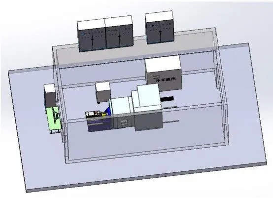
In this article, we will focus on a key piece of equipment - the high-speed single-motor test bench, which is specifically designed to meet the performance and reliability tests of new energy vehicle drive motors and motor controllers. If you are interested in efficient and reliable new energy vehicle motor technology, or want to gain an in-depth understanding of advanced technologies and innovative methods in the motor testing process, then this article will be valuable information you should not miss.
This test bench system is mainly used for the performance and reliability test of new energy vehicle drive motor and motor controller, which meets the technical requirements of the actual test, has superior performance such as technological advancement, high accuracy, high reliability, easy maintenance, and high safety, and meets the relevant standards of national electric vehicle motor drive system testing:
> GB/T 18488.1-2015 Electric vehicle drive motor systems - Part 1: Technical conditions
> GB/T 18488.2-2015 Electric vehicle drive motor systems - Part 2: Test methods
> GB/T 29307-2012 Test method for reliability of drive motor system for electric vehicles
> GB/T 755-2019 Rotary motor quota and performance
> GB/T 22669-2008 Test method for three-phase permanent magnet synchronous motor
> GB/T 1032-2005 Test method for three-phase asynchronous motor
> QC/T 1022-2015 Technical conditions for reducer assemblies for pure electric passenger cars
> GB/T 8196-2003 Machinery safety guards - Design and manufacture of fixed and movable guards - General requirements
> GB/T 4793.1-2007 Safety requirements for electrical equipment for measurement, control and laboratory use - Part 1: General requirements
> GB/T 50055-2011 Design specification for power distribution of general electrical equipment
> GB 5226.1-2008 Mechanical and electrical safety - Mechanical and electrical equipment - Part I: General technical conditions
> ISO 13849-1-2015 Safety-related components for control systems
> GB/T 16855.1-2018 Machinery safety - Safety-related components of control systems
Bench working environment
1. Environment
> Bench room temperature: 5°C~30°C;
> Ambient relative humidity: ≤95%RH;
2. Water supply
> Cooling water: ≤32°C, pressure: 3~4bar;
> Tap water;
3. Compressed air
> 0.6MPa~0.8MPa, industrial grade.
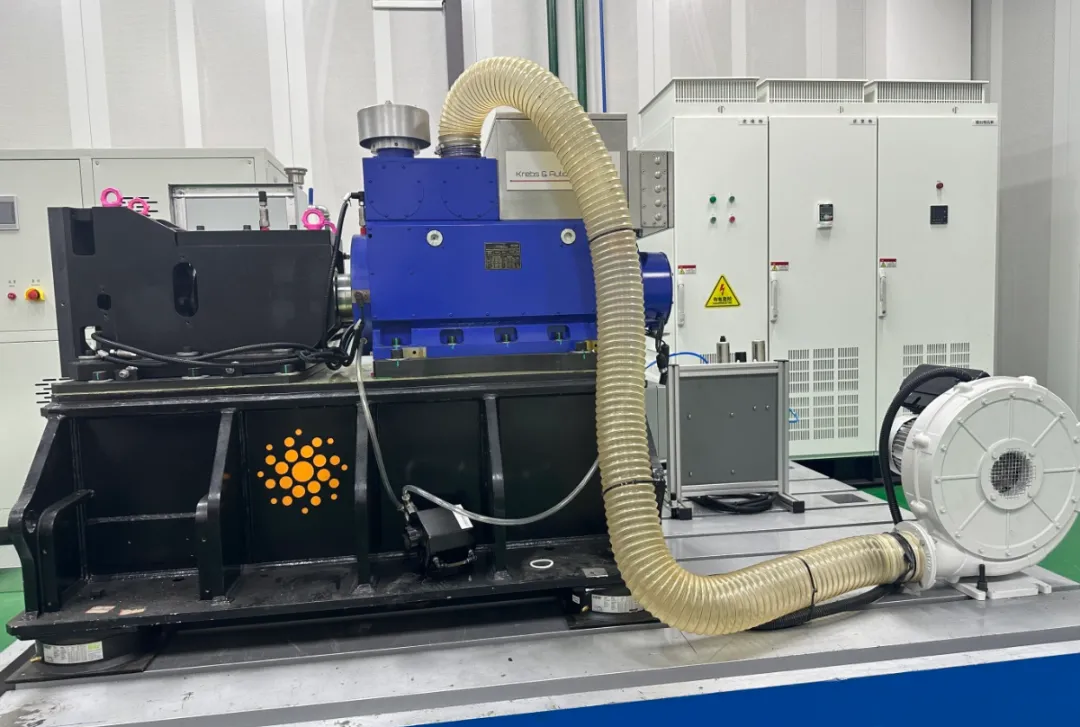
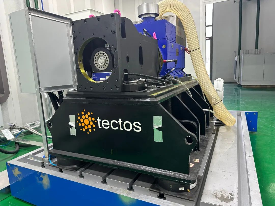
Bench mechanism
The mechanical system as a whole adopts the main high-speed transmission system of the Austrian company tectos. It is the industry's top "test bench special" transmission system and NVH engineering consulting solution company, including but not limited to universal shafts, couplings, prosthetic transmissions, intermediate bearings, docking systems, high-speed electric drive test bench transmission systems, high-speed coaxial lifting boxes, professional drive shaft matching and selection software, bench NVH engineering solutions, high-speed electric drive bench monitoring and protection equipment, product NVH engineering consulting and product development, etc.
Bench accuracy indicators
> Steady-state torque control accuracy: ≤±0.5%FS;
> Torque measurement accuracy: ≤±0.05%FS;
> Steady-state speed control accuracy: ≤±1rpm;
> Speed measurement accuracy: ≤±1rpm;
> System sampling measurement frequency: f≥1kHz.
Main functions of the bench
1) This equipment is a brand new, complete and normal operation equipment.
2) The test bench should be equipped with a safety alarm and interlock shutdown system
> over-limit alarm for speed, torque, temperature, and vibration
> alarm for electrical faults such as overcurrent, overvoltage, undervoltage, and phase break
3) The system is equipped with a control cabinet and an independent computer control and monitoring system.
4) The control monitoring data (such as rotation speed r/min, torque N.m, speed difference r/min, temperature °C) can be detected and displayed in real time on the control cabinet and computer
Recording.
5) The installation plate and all mechanical support parts and connectors have sufficient strength and rigidity, and the mechanical system will not resonate within the scope of the test conditions.
Main functions of the bench
1) This equipment is a brand new, complete and normal operation equipment.
2) The test bench should be equipped with a safety alarm and interlock shutdown system
> over-limit alarm for speed, torque, temperature, and vibration
> alarm for electrical faults such as overcurrent, overvoltage, undervoltage, and phase break
3) The system is equipped with a control cabinet and an independent computer control and monitoring system.
4) The control monitoring data (such as rotation speed r/min, torque N.m, speed difference r/min, temperature °C) can be detected and displayed in real time on the control cabinet and computer
Recording.
5) The installation plate and all mechanical support parts and connectors have sufficient strength and rigidity, and the mechanical system will not resonate within the scope of the test conditions. Technical description of bench equipment
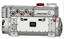
1. Dynamometric motor
Krebs & Aulich motors are selected, which are permanent magnet synchronous motors with high dynamic response characteristics. It is directly connected to the drive shaft system of the motor under test through the power connection shaft.
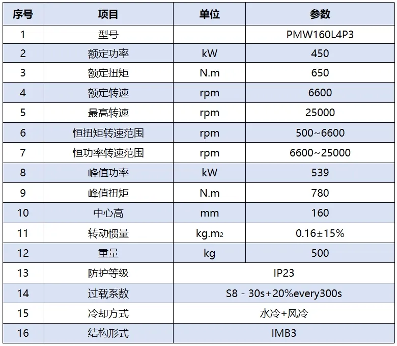
2. Main parameters of the motor:
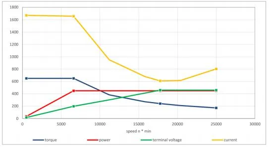
三、电机特性曲线:
Motor drive system
The drive control of the dynamometer motor is realized by the motor drive system, which is composed of power module, inverter module, filter module, etc. The dynamometer is alternating current with 380V and 50Hz
The power grid is connected, and the power module (rectifier/feedback unit) is connected to the power module (rectifier/feedback unit) through the circuit breaker, main contactor, grid-side reactor, and feedback transformer, and connected to the motor downwards through the inverter module (inverter rectifier unit).
Farwide ACS880 is used for the drive system.
No additional software is required, and the standard software can support induction motors, permanent magnet synchronous motors, synchronous reluctance motors, and induction servo motors. With highly accurate direct torque control (DTC), the drive can control the motor both open-loop and closed-loop. Built-in safety features reduce the need for external safety components.
Main parameters of frequency converter
Rectifier unit
> Rectifier Model: ACS880-36-R82-295A-6 AIM B2EC
> quantity: 1 unit
> Rated DC power: 560kW
> supply voltage: 0~1150V
Inverter unit
Inverter model: ACS880-2L8B-2300-6 PSMM PCU E3EC EN224 2HL650
> quantity: 1 unit
Rated power: 2000kW
> Rated output current: 2300A
Torque sensor
The torque sensor of the German HBM company model T40MS is selected and connected to the output shaft end of the dynamometer.
Main technical parameters
> Rated torque: 1000N.m
> Maximum speed: 25000rpm
> Measurement accuracy: ±0.05% F.S
0%~20%FS:≤±0.01%
20%FS~60%FS:≤±0.02%
60%FS~100%FS:≤±0.03%
> Linear error: ≤±0.05%
> Repeatability error: ±0.03%
> Torque transducer with speed measurement
Main technical parameters
> Rated torque: 1000N.m
> Maximum speed: 25000rpm
> Measurement accuracy: ±0.05% F.S
0%~20%FS:≤±0.01%
20%FS~60%FS:≤±0.02%
60%FS~100%FS:≤±0.03%
> Linear error: ≤±0.05%
> Repeatability error: ±0.03%
> Torque transducer with speed measurement
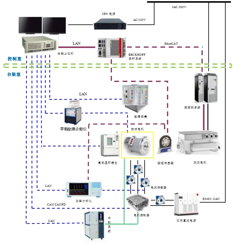
Bench measurement and control system
control all contents in the bench, and the control objects mainly include dynamometer, motor under test, measurement system, condition guarantee system, etc.; The control content includes the test process control of the bench, the setting of loading and running parameters, the measurement parameters, the processing of data recording, the monitoring of motor cooling, the setting of safety parameters, and the monitoring of the operating status of the bench.
The measurement and control system is equipped with domestic famous brand mainstream industrial computers, which realize the effective control of the dynamometer motor through the drive cabinet and realize the collection of test data.
The hardware of the measurement and control system includes the upper computer with the industrial computer as the core, the measurement and control cabinet, the measurement and control unit and other components, and the measurement and control system is equipped with the latest version of the measurement and control software.
Measurement and control system software
The measurement and control system software is divided into two parts: environmental software and measurement and control special software, the special software is the latest version of the AC power dynamometer measurement and control system software developed by our company, which is based on the latest generation of AC power measurement and control system developed on the basis of C Builder.
The special software for measurement and control is divided into two main modules: display parameter setting module and bench measurement and control module. Interface language: Chinese.

Consultation hotline
0574 - 8749 4777
© Copyright 2022 Zhejiang ATTC Automotive Technology Service Co., Ltd


